Inverter & UPS Wiring Planning: A Complete Guide for a Safe and Efficient Home Power Backup System
Power cuts are no longer just an inconvenience — in today's connected world, an unexpected outage can disrupt work-from-home setups, spoil refrigerated food, interrupt medical equipment, and throw an entire household into chaos within minutes. That is exactly why inverter and UPS wiring planning has become one of the most important aspects of modern home construction. At GK Home Construction, we believe that a home built right is a home that runs right — even when the grid does not. Proper wiring for your backup power system is not something you retrofit carelessly after moving in; it is something you design thoughtfully from the very beginning.
Understanding the Difference Between an Inverter and a UPS
Before getting into the wiring details, it is important to understand what you are actually planning for. Many homeowners use the terms "inverter" and "UPS" interchangeably, but they serve different purposes.
An inverter is a device that converts DC (direct current) power stored in batteries into AC (alternating current) power that your home appliances can use. Inverters are ideal for running fans, lights, televisions, and other non-sensitive loads. They come with a small switchover delay — typically 10 to 25 milliseconds — which is barely noticeable for most appliances.
A UPS (Uninterruptible Power Supply), on the other hand, provides zero switchover time. It continuously powers connected devices through its battery system, making it essential for computers, servers, sensitive medical equipment, and any device that cannot tolerate even a millisecond of interruption. UPS systems are generally used for critical, low-load devices, while inverters handle the heavier household loads.
Understanding this distinction is the first step in deciding how many circuits you need, what wiring capacity to plan for, and where to position each unit within the home.
Planning Your Load Calculation First
The biggest mistake most homeowners make is buying an inverter or UPS without first calculating how much power they actually need to back up. Load calculation is the foundation of any good wiring plan.
Start by listing every appliance and device you want to run during a power cut. Note down the wattage of each item — fans typically consume 60 to 80 watts, LED bulbs consume 7 to 15 watts, a television draws around 80 to 150 watts, and a refrigerator can pull anywhere from 150 to 300 watts depending on the model. Add all these values together to determine your total load in watts.
Once you have your total wattage, you can choose the right inverter capacity — usually expressed in VA (volt-amperes). A general rule is to divide your total wattage by 0.8 (the average power factor) to get the required VA rating. For example, a total load of 800 watts would require a minimum 1000 VA inverter. Always add a 20 to 25 percent buffer on top of this to avoid overloading the system and to allow for future additions.
This load calculation directly influences the wire gauge, circuit breaker ratings, and the battery bank size you plan into your home's wiring layout.
Choosing the Right Location for Your Inverter and Battery
Wiring planning is directly tied to where you physically place your inverter and battery bank. This is a decision that needs to be made during the construction or renovation phase, not after the walls are finished.
The ideal location for an inverter is a well-ventilated room or dedicated utility area, away from direct sunlight, moisture, and flammable materials. Batteries — especially tubular lead-acid batteries — release small amounts of hydrogen gas during charging, which means the room must have adequate ventilation or an exhaust provision. Lithium-ion batteries are safer in enclosed spaces, but ventilation is still good practice.
The inverter should be placed as close as possible to the battery bank to minimize DC cable length. Longer DC cables result in higher resistance, voltage drop, and heat generation — all of which reduce efficiency and can become safety hazards over time. Ideally, the DC cable run between the battery and inverter should not exceed 1.5 to 2 metres. If the distance must be greater, you will need to step up the cable thickness accordingly.
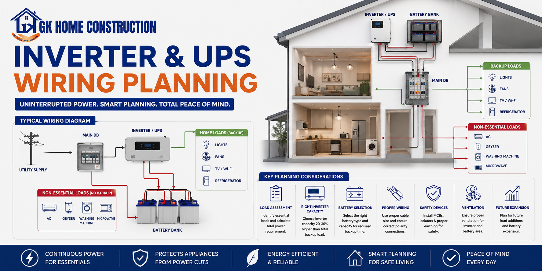
Wiring the Inverter into Your Home's Electrical Circuit
This is the most technical and critical part of the entire planning process, and it must be handled by a licensed electrician. The standard approach in Indian homes is to create a dedicated "inverter circuit" that runs parallel to the main electrical supply.
In this setup, your home has two types of circuits: the main grid circuit and the inverter-backed circuit. The inverter-backed circuit covers selected loads — usually lights, fans, a few power sockets, and perhaps the television. The heavier loads like air conditioners, geysers, and washing machines typically remain on the main grid circuit only, since running them on an inverter would drain the battery rapidly.
A changeover switch or Automatic Transfer Switch (ATS) is installed to manage the transition between grid power and inverter power. When the mains supply fails, the ATS automatically disconnects the home from the grid and connects it to the inverter output. This prevents back-feeding of inverter power into the grid, which is both dangerous and illegal.
The wiring for inverter circuits should use copper conductors with the appropriate gauge — typically 4 sq.mm to 6 sq.mm for the main inverter output line, and 1.5 sq.mm to 2.5 sq.mm for branch circuits depending on the load. All connections must be properly terminated with lugs, covered with insulating tape, and routed through conduits to prevent mechanical damage.
Battery Wiring and Safety Provisions
The DC side of the wiring — between batteries and the inverter — demands the same level of attention as the AC side. Use flexible, multi-strand copper cables rated for the full short-circuit current of the battery bank. All DC cables must be fused as close to the battery terminals as possible. This fuse protects the cable from fire in the event of a short circuit.
Battery terminals should be kept clean, coated lightly with petroleum jelly to prevent corrosion, and secured with properly sized terminal lugs. Loose battery connections are one of the most common causes of inverter malfunction and fire hazards in Indian homes. Additionally, if you are using a battery bank with multiple batteries connected in series or parallel, ensure uniform cable lengths and matching wire gauges across all connections to maintain balanced charging and discharging.
Earthing and Surge Protection
No inverter or UPS wiring plan is complete without proper earthing and surge protection. The inverter chassis must be connected to the home's earthing system. A good earth connection protects you from electric shock and also helps the inverter's built-in protection circuits operate correctly.
Install a good-quality surge protection device (SPD) or voltage stabilizer on the input side of the inverter if your area experiences frequent voltage fluctuations. Many inverters have built-in protection, but an external SPD adds a valuable extra layer of security.
Final Thought: Plan It Right, Build It Once
Inverter and UPS wiring planning is not an afterthought — it is an integral part of designing a safe, functional, and future-ready home. Whether you are building a new house or undertaking a major renovation, routing the right conduits, sizing your cables correctly, and positioning your equipment thoughtfully from day one will save you significant cost, effort, and risk down the line. At GK Home Construction, we integrate backup power planning into every project we undertake, because a truly well-built home is one that stands strong even when the lights go out.